
 English
Views: 0 Author: Site Editor Publish Time: 2026-08-15 Origin: Site


The most frequent point of failure in an Automated Motorized Total Station (AMTS) system is not the robotic instrument itself, but the geometric integrity and physical stability of the optical target network. Misclassifying target types, or failing to secure stable control geometry, results in contaminated data. When reference targets move or monitoring targets suffer localized flex, the system generates false movement vectors. This leads to costly false alarms, halted construction, or missed catastrophic failures.
Architecting a defensible AMTS network requires a strict operational distinction between moving assets and static control. This guide breaks down the functional differences, hardware selection criteria, and implementation realities of monitoring points versus reference points to ensure high-fidelity deformation data.
Strict Functional Separation: Reference points establish the AMTS's coordinate system and must remain absolutely static outside the Zone of Influence (ZOI); monitoring points track the actual deformation of the asset.
Hardware Asymmetry: Do not use identical hardware setups universally. Reference points require high-precision, environmentally shielded prisms on rigid mounts, while monitoring points prioritize cost-effective, low-profile form factors suitable for high-volume deployment.
The "Moving Control" Risk: The most critical threat to data integrity is a reference point that subtly deforms due to thermal expansion, ground settlement, or poor bracket design, which the software will falsely interpret as movement of the monitored structure.
Prism Constant Alignment: Mixing different monitoring prism types without auditing their physical offsets (prism constants) introduces systemic, millimeter-level mathematical errors during coordinate calculation.
Redundancy is Mandatory: A robust network requires a minimum of 3 to 5 stable reference points per AMTS to allow for rigorous least-squares network adjustment and to isolate compromised control points.
An AMTS utilizes line-of-sight measurements to calculate 3D coordinates over time. The instrument emits an infrared laser to an optical target, measuring the slope distance, horizontal angle, and vertical angle. By repeating these measurements at scheduled intervals, the system tracks millimeter-level changes in the physical environment. The reliability of these calculations depends entirely on the physical targets reflecting the signal.
Network design relies on a fundamental division of labor between targets. You use reference points, or control targets, strictly for instrument orientation. These establish the spatial baseline. Conversely, you use deformation targets to evaluate the asset itself. A monitoring prism installed on a retaining wall tells you how the wall behaves, but only if the instrument first proves its own location by sighting the static reference points.
Every optical target has a specific prism constant, such as 0mm, -17.5mm, or -34.4mm. This value represents the physical alignment of the prism glass center point relative to its mounting axis. If the software does not account for this offset, the distance measurement will be mathematically flawed. Beam deviation also impacts absolute measurement accuracy. High-quality glass minimizes the spread of the returning laser beam, ensuring the instrument reads the exact center of the target rather than a distorted reflection.
Monitoring software processes these two data streams differently during the free-stationing or resection calculation. Programs like Leica GeoMoS or Trimble 4D Control assume reference points have fixed coordinates. The software uses these fixed points to calculate the current position of the AMTS. Once the instrument position is mathematically locked, the software measures the deformation points and records any spatial delta as actual structural movement.
To execute a proper resection, the system follows a specific sequence:
The AMTS wakes up and turns to the programmed horizontal and vertical angles for the first reference point.
The instrument performs an automatic target recognition (ATR) scan to lock onto the exact optical center of the prism.
It records the distance and angle, then repeats this process for the remaining reference points in the network.
The software runs a least-squares adjustment to calculate the instrument's current X, Y, and Z coordinates, along with its orientation.
Only after passing the statistical quality check for the resection does the instrument begin measuring the deformation targets.
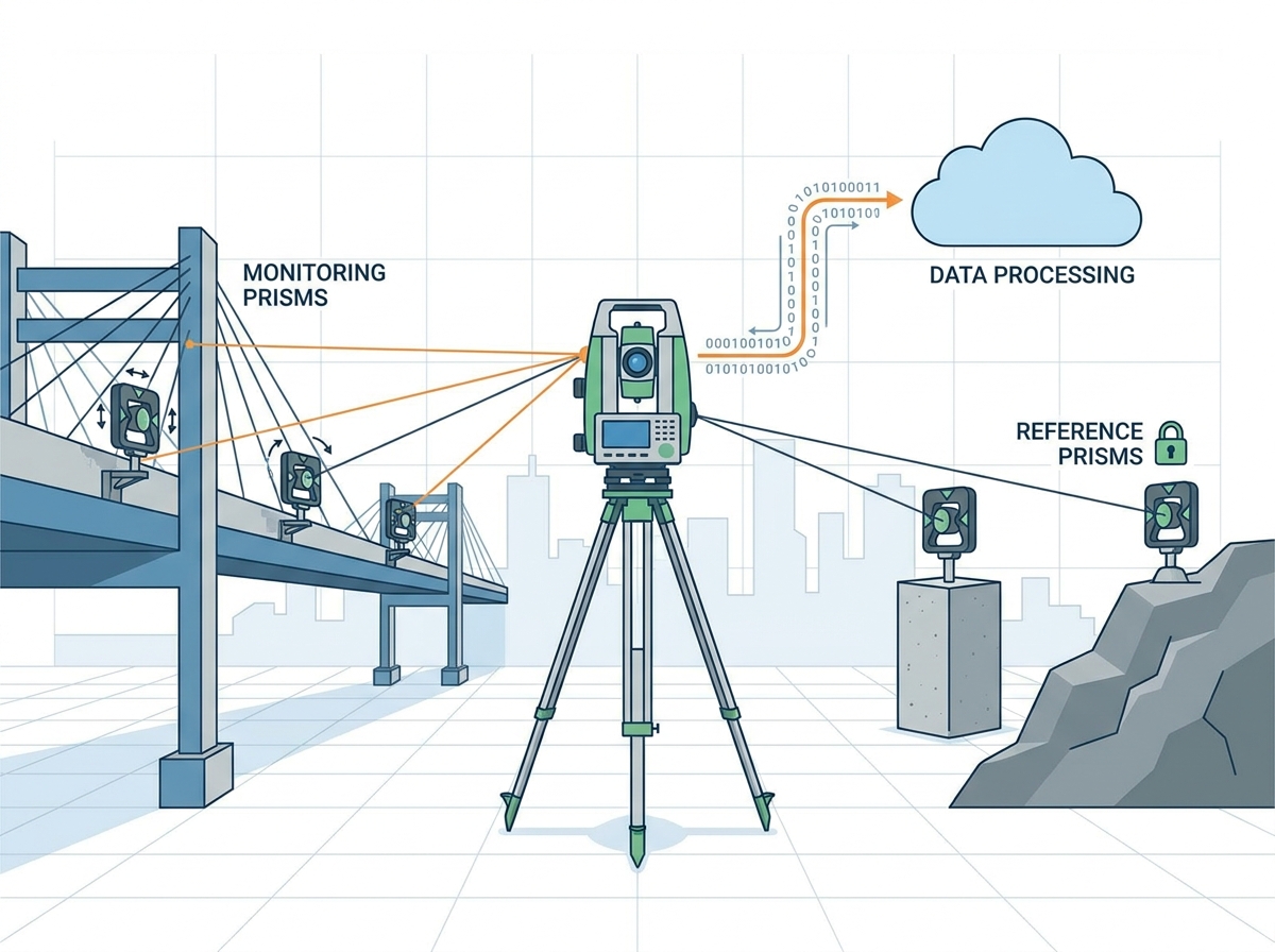
A reference point is a target with fixed, known coordinates used to determine the AMTS's position and orientation for every measurement cycle. The primary success metric for this target is absolute immobility. You must locate the point strictly outside the anticipated Zone of Influence (ZOI) of the excavation, tunneling, or construction activity. If the ground around the reference point shifts, the entire coordinate system collapses.
Reference points require robust hardware. Specify high-precision L-bar prisms, shielded circular prisms, or specialized 360-degree prisms if multiple AMTS units share the same control network. Reference prisms require high-grade optical glass with low beam deviation, typically under 2 arcseconds. They also need silver or copper back-coatings to prevent reflectivity loss over time due to moisture or oxidation.
Mounting requirements are equally stringent. Install deep foundation anchors, embed the mounts into bedrock, or attach them to massive, thermally stable adjacent structures. You must avoid cantilevered brackets subject to wind vibration or thermal expansion. When drilling into concrete for a reference point, use high-strength structural epoxy and allow it to cure fully before attaching the prism bracket. Mechanical wedge anchors can slip under dynamic loads, compromising the control geometry.
Engineers face a constant trade-off between placing reference points far away to ensure stability and keeping them close enough to maintain high optical accuracy. Long sightlines increase the risk of atmospheric refraction, where heat waves distort the laser beam. However, placing them too close risks encroachment by the expanding ZOI. Furthermore, reference prisms require periodic cleaning to maintain signal strength. Placement must balance absolute immobility with safe physical access for maintenance crews.
A monitoring point is a target installed directly on the asset of interest. You expect the coordinates of this point to change. The primary success metric is high-fidelity coupling to the structure. The target must move exactly as the structure moves, without independent vibration, bracket sag, or localized distortion.
Following a reliable structural monitoring prism guide helps differentiate between mini-prisms and standard 62mm prisms. Mini-prisms offer a low-profile form factor ideal for short-range measurements and discrete installations. Standard 62mm prisms provide the larger reflective surface required for long-range visibility. Mounting configurations vary widely. Swivel mounts, L-bars, anchor bolts, and magnetic bases suit different substrates like concrete, structural steel, or masonry. Since projects often require hundreds of monitoring points compared to a handful of reference points, you must balance unit cost with optical reliability to scale the deployment effectively.
Environmental degradation threatens long-term data integrity. Dust accumulation, moisture ingress, and UV damage to coatings degrade signal return over multi-year projects. Integrated rain and dust hoods provide essential protection. You must also address physical risks. Vandalism, accidental damage by construction equipment, and dynamic line-of-sight obstructions like cranes or scaffolding require careful site planning and robust protective housings.
When installing deformation targets on a slurry wall or secant pile wall, the coupling method dictates the data quality. Shooting a concrete nail through a plastic prism housing is insufficient. You must drill and set a threaded rod into the concrete, then thread the prism housing directly onto the rod. This ensures any movement recorded by the AMTS reflects actual deflection of the retaining wall, rather than the plastic housing warping in the afternoon sun.
Understanding the hardware differences requires a direct comparison of technical specifications. You cannot treat all optical targets as interchangeable commodities. The physical demands placed on a control point far exceed those placed on a deformation target.
Specification | Reference Points (Control) | Monitoring Points (Deformation) |
|---|---|---|
Beam Deviation | High precision (<2" to 3") | Standard (5" to 10") |
Prism Constant Stability | Absolute consistency required | Variable options acceptable |
Coating Material | Copper/Silver (weather-resistant) | Budget Anti-Reflex or No Coating |
Mounting Rigidity | Bedrock/Deep anchors | Surface mounts/L-bars |
Housing Material | Machined aluminum or stainless steel | High-impact polymer or light alloy |
Redundancy is a mathematical necessity for reference points. You need a minimum of 3 to 5 stable points to enable statistical outlier detection. If one control point is compromised, the software can isolate it and calculate the instrument position using the remaining points. Contrast this with monitoring point density, which is dictated by structural engineering requirements. You space deformation targets based on expected stress intervals along a slurry wall or tunnel crown, rather than surveying geometry.
Over-engineering monitoring points introduces unnecessary project expenses, especially when deploying hundreds of units. Conversely, under-engineering reference points guarantees systemic data failure. You must allocate the budget heavily toward control stability. Additionally, reference points often require longer sightlines to remain outside the ZOI. You mitigate the resulting atmospheric errors by scheduling redundant observations and utilizing time-of-day averaging algorithms.
A cascading data failure occurs when a reference point enters the ZOI or settles independently. The software attempts to calculate the instrument position using a compromised baseline. This projects false movement vectors onto every monitoring point in the network. Software identifies this through high residual errors during the resection calculation. You must quarantine the bad point immediately to restore network integrity.
Entering an incorrect prism constant in the software during system configuration creates a systematic scaling error across the network. If the physical target has a -17.5mm offset but the software expects 0mm, every distance measurement will be skewed. This corrupts the coordinate system from the first measurement cycle.
Long metal mounting brackets expand and contract with diurnal temperature changes. The software records this thermal flex as structural movement, triggering false alarms. Mitigation strategies include using short brackets, invar steel mounts, physical shading, and robust anchor selection to eliminate localized distortion.
Heat shimmer and temperature gradients bend the optical line of sight. This disproportionately affects distant reference points. A beam passing over an asphalt road on a hot afternoon will refract upward, altering the vertical angle measurement. You mitigate this via redundant observations and averaging measurements taken during stable atmospheric windows, such as pre-dawn hours.
Rain, dew, ice, and dust accumulation degrade the signal return. The instrument struggles to lock onto the target, leading to measurement timeouts or inaccurate return readings. Using heated prisms prevents ice and dew formation, while hydrophobic-coated glass repels water and dust, maintaining clear sightlines in harsh environments.
A reliable AMTS network depends on maintaining a strict distinction between reference points and monitoring points. Reference prisms define the coordinate system and must remain stable outside the Zone of Influence, while monitoring prisms must be rigidly coupled to the structure so their movement accurately represents real deformation.
Reference points therefore require higher-precision optics, durable mounts, stable foundations, and sufficient redundancy for least-squares adjustment and outlier detection. Monitoring points can use more economical hardware, but their mounting geometry, visibility, and environmental protection still directly affect data quality.
Prism constants must match the software configuration exactly, especially in mixed-target networks. Regular checks for bracket movement, thermal distortion, contamination, and declining signal strength are also essential. Accurate deformation data begins with stable control geometry—not software correction after the network has already shifted.
A: A reference point is a static target located outside the zone of influence used to establish the instrument's coordinates. A monitoring point is installed directly on the structure to track actual physical deformation over time.
A: Prism constants dictate the physical offset of the glass center. If the software configuration does not match the physical target's constant, it introduces systematic distance errors, skewing all coordinate calculations.
A: A robust network requires a minimum of 3 to 5 stable reference points. This redundancy allows the software to perform least-squares adjustments and identify if a single control point has moved.
A: Technically yes, but it is highly discouraged. Monitoring prisms often lack the high-precision glass, low beam deviation, and durable weather coatings required for long-term, stable control measurements.
A: Software detects reference point movement by analyzing residual errors during the resection calculation. If the distances and angles between control points change, the system flags the anomalous point for quarantine.
A: Copper or silver back-coatings are best for long-term installations. They prevent oxidation, resist moisture ingress, and maintain high reflectivity over multi-year projects compared to uncoated or standard anti-reflex glass.