
 English
Views: 0 Author: Site Editor Publish Time: 2026-07-13 Origin: Site


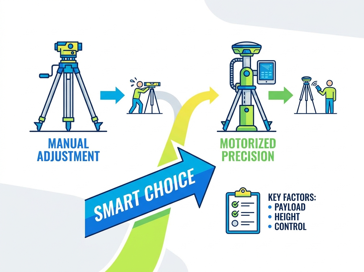
Elevating high-value surveying instruments, such as 3D laser scanners and robotic total stations, is necessary to eliminate line-of-sight occlusions. Doing so introduces significant risks to both equipment safety and data integrity. Manual crank tripods are inefficient and pose ergonomic hazards when lifting heavy payloads. They often lack the torsional rigidity required to prevent micro-vibrations. This structural weakness leads directly to point cloud registration errors or inaccurate total station measurements in the field.
Selecting the right motorized elevation tripod for surveying instruments requires a rigorous evaluation of payload dynamics, stability metrics, power management, and operational environments. Field crews cannot afford equipment failure when suspending delicate optics meters above the ground. This guide breaks down the technical criteria for making an evidence-based procurement decision, ensuring your hardware investments remain secure while capturing flawless spatial data.
Payload Matching is Non-Negotiable: The tripod’s dynamic lifting capacity must exceed the combined weight of the instrument, tribrach, and adapters to prevent motor burnout and ensure smooth elevation.
Height vs. Stability Trade-off: Maximum elevation directly impacts torsional rigidity; evaluating the inclusion of guy-wire systems or secondary bracing is critical for heights exceeding 3 meters.
Active Verticality and Leveling: Maintaining millimeter-level verticality during and after vertical transit is paramount; buyer preference should lean toward systems with integrated tilt monitoring or self-correcting leveling bases.
Vibration Dampening Dictates Data Quality: The structural material (heavy-duty aluminum vs. carbon fiber composites) and drive mechanism dictate how quickly the system dampens operational and environmental vibrations.
The primary function of any elevation system is achieving necessary height without compromising the millimeter-level accuracy of the instrument. Surveyors face a constant battle against physical obstructions. Elevating a scanner or total station expands the field of view, drastically reducing the total number of setups required for a project. However, this height introduces leverage forces. A successful deployment means the tripod absorbs these forces, keeping the instrument perfectly plumb and stable throughout the entire data capture cycle. You need a platform that acts as a rigid extension of the ground itself, regardless of the extension height.
When you push a scanner three or four meters into the air, the wind profile changes. Ground-level breezes become sustained gusts at elevation. The tripod must resist these lateral forces. If the center column flexes even a fraction of a degree, the angular error at a distance of fifty meters becomes unacceptable. Baseline requirements dictate that the mechanical lifting system must not introduce any play or slop into the setup. Every gear, locking collar, and leg hinge must lock down with absolute certainty.
Complex environments demand elevated perspectives. Open-pit mining operations require high vantage points to scan deep excavations safely. Busy construction sites feature constant material movement, blocking ground-level sightlines. Structural monitoring, forestry canopy analysis, and forensic scene reconstruction all benefit from an elevated optical center. By utilizing a motorized system, survey teams can lift sensors above site clutter. This strategic positioning captures cleaner data, minimizes shadow zones in point clouds, and accelerates the overall field workflow.
Consider a standard highway overpass survey. Ground-level setups require dozens of station moves to see around concrete pillars and temporary falsework. By elevating the scanner, you can shoot over the top of jersey barriers and construction equipment. This reduces field time and limits the exposure of your survey crew to active traffic lanes. The motorized lift allows a single operator to manage the heavy lifting safely, keeping the project moving without requiring additional personnel for setup.
Not all scanning requires upward elevation. Infrastructure projects frequently involve downward or inverted scanning in vertical shafts, sewer access points, and multi-level structural voids. Standard tripods cannot accommodate these geometries. Specialized motorized systems feature secure underslung mounting assemblies. These mounts allow operators to lower expensive scanners into confined spaces with precise control. The motorized mechanism ensures a steady descent, preventing accidental collisions with shaft walls while maintaining a rigid connection for accurate spatial mapping.
When scanning a deep utility manhole, dropping a scanner on a manual winch is a massive liability. The payload swings, and the descent rate is uneven. A motorized system with a geared drive provides a controlled, millimeter-by-millimeter descent. You can stop the instrument at exact depth intervals, lock the drive, and initiate a scan with confidence that the unit is stable. This capability transforms hazardous confined space entries into routine remote data capture operations.
Surveying instruments represent massive capital investments. Manual hoisting relies on human strength and introduces the risk of catastrophic drops. Motorized lifting replaces this physical strain with controlled ascent and descent profiles. Integrated anti-drop braking mechanisms lock the column instantly if power is lost. This mechanical redundancy protects the payload from gravity-induced freefalls. Relying on electronic and mechanical fail-safes provides peace of mind when suspending fragile optical equipment high above concrete surfaces.
Ergonomics also play a massive role in risk mitigation. Asking a technician to manually crank a 15-kilogram scanner up to four meters multiple times a day leads to fatigue. Fatigue leads to mistakes, such as failing to engage a locking collar properly. Motorized systems remove the physical exertion from the equation. The operator presses a button, and the machine handles the heavy lifting. This keeps the crew fresh, focused on data quality, and significantly reduces the likelihood of workplace lifting injuries.
Evaluating load ratings requires distinguishing between static and dynamic capacities. Static load capacity refers to the maximum weight the tripod can support when fully locked in position. Dynamic load capacity dictates the weight the motor can actively lift without stalling or overheating. Always size the tripod based on the dynamic rating. Furthermore, the instrument's center of gravity drastically affects performance. A top-heavy scanner places lateral strain on the drive shaft and top plate. Ensuring the payload remains perfectly centered minimizes motor wear and prevents asymmetrical column deflection.
If you mount a heavy robotic total station off-center, the uneven weight distribution forces the internal gears to grind against one side of the column housing. Over time, this uneven wear destroys the lifting mechanism. You must calculate the total weight of your heaviest setup. This includes the instrument, the tribrach, any quick-release adapters, and external batteries mounted on the instrument. If your total payload is 12 kilograms, you need a tripod with a dynamic rating of at least 15 to 20 kilograms to ensure the motor operates efficiently without straining.
Payload Type | Average Weight (kg) | Recommended Dynamic Capacity (kg) | Center of Gravity Considerations |
|---|---|---|---|
Standard 3D Laser Scanner | 5 - 8 | 15 | Usually well-centered; standard tribrach sufficient. |
Heavy-Duty Robotic Total Station | 8 - 12 | 20 | Can be top-heavy; requires wide-stance top plate. |
Scanner + External Battery + GNSS Rover | 12 - 18 | 25+ | Highly asymmetrical; requires counter-balancing or heavy-duty gearing. |
The connection point between the instrument and the tripod is a critical vulnerability zone. Standard 5/8" x 11 threaded mounts are common, but heavy payloads often require specialized tribrach mounts or quick-release adapters. These interfaces must mitigate lateral slippage during vertical transit. Evaluate the machining tolerance of the top plate. Even a fraction of a millimeter of micro-play under load will translate to massive angular errors at the sensor level. Solid billet aluminum plates with locking set screws provide the necessary rigidity for high-precision tasks.
Avoid stamped metal top plates entirely. They flex under load. You want a thick, CNC-machined platform. When the motor engages, the initial torque transfers directly through this plate. If the plate flexes, the instrument jerks. Look for systems that utilize a three-point locking mechanism for the tribrach, ensuring the instrument cannot rotate independently of the column. The connection must be absolute.
Reach and portability exist in constant tension. Maximum reach often spans three to five meters, providing excellent line-of-sight clearance. However, this extended height requires longer leg sections and taller center columns. Evaluate the retracted length to ensure the unit fits inside standard utility vehicles or transport cases. Multi-section telescopic columns achieve higher elevations but introduce tolerance buildup. Every joint and locking collar represents a potential point of flex. Fewer, thicker column sections generally provide better structural integrity than numerous thin sections.
A tripod that reaches five meters but collapses down to two meters is highly portable but likely relies on three or four telescopic sections. Each of those sections has a slight gap to allow movement. When fully extended, those gaps compound, creating a wobble at the top. A two-section column is inherently stiffer but will have a longer retracted length, potentially requiring a custom roof rack for transport. You must balance your need for height against your logistical transport capabilities.
The internal drive mechanism dictates operational smoothness. Direct-drive motors offer high torque but can be heavy. Geared mechanisms, such as worm drives, provide excellent holding power and naturally resist back-driving under load. Rack-and-pinion or belt systems offer faster lifting speeds but may require more frequent tension maintenance. Lifting speed, measured in millimeters per second, should prioritize smoothness over raw velocity. Soft-start and soft-stop electronic controls are mandatory. These features ramp the motor speed up and down gradually, preventing sudden inertia jolts that could misalign the instrument's internal compensators.
A worm drive is generally the preferred mechanism for heavy surveying payloads. Because of the gear geometry, a worm drive cannot be driven backward by the weight of the payload. If the motor loses power, the gear locks in place automatically. Belt drives, while smooth and quiet, can stretch over time and require tensioning. If a belt snaps, the payload relies entirely on secondary emergency brakes. Always prioritize mechanical holding power over lifting speed.
Operator safety improves when personnel remain outside the potential fall zone during elevation. Wired hand-control pendants are reliable and immune to signal jamming, but they tether the operator to the tripod. Wireless control systems utilizing Bluetooth or RF frequencies offer superior mobility. When evaluating wireless options, consider interference resistance in dense urban environments or active construction sites. Mobile app integrations provide advanced telemetry, but dedicated physical remotes often offer better tactile feedback. Fine-adjustment height controls are essential for targeting specific horizontal scan lines or aligning with structural datums.
When working near high-voltage power lines or active cell towers, RF interference can sever the connection to a wireless remote. In these environments, a hardwired pendant is the only reliable option. Look for systems that offer both. You want the freedom of a wireless remote for standard operations, with a plug-in cable backup for high-interference zones. The remote should feature large, tactile buttons that you can operate while wearing heavy work gloves.
Gravity is the constant enemy of elevated payloads. Mechanical auto-locking brakes must engage the moment the motor stops or power is interrupted. Electronic slip clutches protect the internal gearing. If the ascending column strikes an overhead obstruction, the clutch slips, preventing motor burnout and structural buckling. Emergency stop buttons must be prominently located on both the remote and the main control housing. Striking the E-stop should instantly sever power to the drive system and engage all mechanical braking mechanisms.
Imagine elevating a scanner inside an industrial facility. The operator misjudges the clearance, and the top of the scanner hits a steel I-beam. Without a slip clutch, the motor will continue to push upward. This will either crush the scanner housing, burn out the motor, or tip the entire tripod over. A properly calibrated slip clutch will disengage the drive instantly upon impact, saving your equipment from destruction.
Electrical systems can fail in harsh field conditions. A dead battery, a severed cable, or a blown fuse should never strand a high-value instrument five meters in the air. A manual recovery override is a non-negotiable feature. This mechanism typically involves a hand crank socket that bypasses the electronic drive. Operators can safely lower the payload using physical force. The manual descent must remain geared to prevent the column from dropping too quickly, ensuring the instrument returns to ground level without impact damage.
The manual override must be accessible without requiring specialized tools. If the system dies, you should be able to attach a standard socket wrench or an included hand crank and bring the instrument down immediately. Test this feature during your initial equipment evaluation. If the manual crank requires excessive force or feels jerky, the internal gearing is poorly designed.
Twisting motions, known as yaw, are fatal to panoramic 3D laser scans. As the scanner rotates, any torsional flex in the tripod column warps the resulting point cloud. Leg spread ratios must be wide enough to counteract this rotational force. Leg lock mechanisms and column locking collars must clamp down with absolute zero tolerance. Establish acceptable wind load thresholds before deployment. High winds create a sail effect on the elevated instrument. If the wind exceeds the manufacturer's rated threshold, data degradation is guaranteed, and the setup must be lowered.
To maximize torsional rigidity, always deploy the tripod legs to their widest possible stance. A narrow footprint might save space on a crowded sidewalk, but it sacrifices stability. When the scanner head spins at high speeds, it generates rotational inertia. The tripod must absorb this energy. If you notice the point cloud data showing a slight twist or misalignment at the edges of the scan, your tripod is flexing under the rotational load.
Vibrations originate from two sources: the surrounding environment and the internal motor. The material science of the tripod dictates its vibration absorption coefficients. Heavy-duty aluminum offers excellent rigidity but can transmit high-frequency vibrations. Carbon fiber composites excel at dampening micro-vibrations quickly, though they require careful handling to prevent impact fractures. Internal motor vibrations must be isolated from the top plate. Rubberized dampening mounts between the drive shaft and the mounting interface prevent motor harmonics from reaching the sensitive optical sensors during transit.
If you are setting up on a bridge deck with active traffic, the concrete will transmit low-frequency rumbles directly into the tripod legs. Aluminum legs will carry those vibrations straight up to the instrument. Carbon fiber or heavy fiberglass legs will absorb and dissipate a significant portion of that energy before it reaches the top plate. Choose your tripod material based on the environments you work in most frequently.
Elevating a column shifts the center of mass. The system must maintain plumb and level during the entire elevation process. Any deviation introduces angular errors into the survey data. High-end systems utilize precision-machined guide rails to prevent lateral drift. Surveyors must rely on the dual-axis compensator monitoring built into the surveying instrument. Checking the electronic bubble before and after vertical transit verifies that the elevation process has not knocked the setup out of level. Self-correcting leveling bases offer an automated solution to this persistent challenge.
Follow a strict leveling protocol. Level the tripod manually at the base. Elevate the column to the desired height. Check the instrument's electronic level. If it has drifted out of tolerance, you must lower the column, re-level the base, and try again. Never attempt to adjust the base leg lengths while the payload is elevated. This shifts the center of gravity dangerously and can cause the entire setup to collapse.
When pushing maximum height limits, the tripod legs alone cannot guarantee stability. Secondary stabilization becomes mandatory based on height, payload weight, and environmental wind conditions. Guy-wire systems anchor the top of the column to the ground, drastically increasing torsional rigidity and wind resistance. Rigid strut braces connecting the center column to the tripod legs offer another layer of reinforcement. While deploying guying systems incurs a setup time penalty, the data quality guarantee makes it a necessary step for precision scanning at extreme elevations.
Deploying a guy-wire system requires specific steps to ensure even tension:
Elevate the column to approximately 50% of the target height.
Attach the three guy wires to the designated anchor ring on the top plate.
Stake the wires into the ground at a 45-degree angle from the column, spaced 120 degrees apart.
Elevate the column to the final height, allowing the wires to pull taut.
Use inline tensioners to make micro-adjustments, ensuring the column remains perfectly plumb.
Motorized lifting requires robust power management. Integrated lithium-ion batteries offer clean, cable-free operation but face capacity limits. External 12V marine batteries provide massive capacity for multi-day projects but add significant weight to the gear loadout. Direct AC power is ideal for long-term structural monitoring but is rarely available in remote areas. Extreme cold degrades lithium-ion performance rapidly. Field crews operating in freezing conditions require hot-swappable power solutions or cold-weather battery warming sleeves to ensure the motor retains enough torque to lift heavy payloads.
If you are working in sub-zero temperatures, keep your spare batteries inside the cab of your truck with the heater running. A cold-soaked lithium-ion battery will lose up to 50% of its effective capacity and may not output enough amperage to drive the motor under full load. Swap the warm battery into the tripod right before you need to elevate the instrument. Once the scan is complete, pull the battery and return it to the warm truck.
The true weight of the system includes the tripod, motor, batteries, and control units. This combined mass directly impacts single-operator deployment capabilities. Heavy systems require two-person lifting protocols to prevent workplace injuries. Transport options must mitigate this weight. Heavy-duty transit cases with custom foam inserts protect the mechanics during transit. Integrated wheel kits and ergonomic handles allow operators to traverse rough terrain without exhausting themselves before the survey begins. Crews flying to remote project sites must also verify that all lithium-ion batteries comply with strict IATA transport regulations.
A fully equipped motorized tripod can easily weigh over 30 kilograms. Carrying that across a muddy construction site is not feasible for one person. Look for systems that break down into modular components. If you can detach the motor housing and battery pack from the main leg assembly, you can transport the system in two manageable trips. This modularity saves backs and prevents accidental drops during transport.
Surveying happens in the dirt, mud, and rain. The motorized components must survive these realities. Define the minimum Ingress Protection (IP) rating required for your typical environments. An IP54 rating handles light dust and splashing water, while IP65 or higher is necessary for heavy rain and fine particulate exposure. The telescopic column seals require specific attention. Abrasive job site dust, salt water, or concrete slurry can destroy internal seals rapidly. Regular wipe-downs and adherence to the manufacturer's maintenance schedule are required to keep the elevation mechanism functioning smoothly.
Never retract a dirty column. If you have been working in a dusty environment, the exposed sections of the telescopic column will be coated in grit. If you power the column down, that grit gets dragged past the wiper seals and into the internal gearing. Always wipe the column down with a clean, dry microfiber cloth before retracting it. This simple habit will extend the life of your motor and seals by years.
A motorized elevation tripod is a critical piece of data-capture infrastructure. It bridges the gap between the theoretical capabilities of your optical instruments and the physical limitations of complex job sites. By removing manual lifting hazards and providing unmatched stability at height, these systems protect your hardware while ensuring the spatial data remains mathematically sound.
When evaluating options, prioritize dynamic payload capacity and mechanical safety fail-safes above all else. Once the safety of the instrument is guaranteed, filter your choices based on maximum required height, torsional rigidity, and environmental weather ratings. A well-matched system will seamlessly integrate into your existing field workflow.
Take the following steps to finalize your equipment selection:
Calculate the exact dynamic weight of your heaviest instrument configuration, including all tribrachs and adapters.
Verify the IP rating of the motor and control unit against the harshest weather conditions your team typically encounters.
Request an on-site demonstration to test real-world vibration dampening and vertical tracking accuracy.
Contact us to discuss specific mounting interfaces and power management solutions for your next deployment.
A: Most professional-grade motorized tripods offer maximum elevations between 3 and 5 meters. Specialized heavy-duty models can reach up to 6 meters, though heights exceeding 3 meters typically require secondary guy-wire bracing to maintain the torsional rigidity necessary for accurate surveying.
A: Yes. High-quality motorized tripods are engineered specifically for 3D laser scanning. They utilize precision-machined columns, heavy-duty leg locks, and vibration-dampening materials to prevent the micro-movements and torsional flex that cause point cloud registration errors.
A: Dynamic payload capacities vary by manufacturer, but heavy-duty models typically lift between 15 kg and 30 kg safely. Always ensure your combined instrument and adapter weight falls well below the maximum dynamic rating to prevent motor strain.
A: Professional systems feature mechanical auto-locking brakes that engage instantly upon power loss, preventing the column from dropping. Operators can then use a manual recovery override crank to safely lower the instrument back to ground level.
A: Yes, many motorized tripods support inverse scanning. This requires a specialized underslung mounting assembly that securely attaches the instrument beneath the tripod head, allowing the motor to carefully lower the scanner into vertical shafts or manholes.