
 English
Views: 0 Author: Site Editor Publish Time: 2026-08-01 Origin: Site


Deploying high-value payloads like 3D laser scanners, advanced surveying instruments, and LiDAR sensors at elevation carries high financial and operational stakes. A single tip-over or structural failure destroys tens of thousands of dollars in hardware, causes catastrophic data loss, and creates severe project delays. Job sites rarely offer ideal, controlled conditions. Uneven terrain, variable soil density, high wind loads, overhead utility hazards, ground vibrations, and operator error introduce severe risks when extending heavy equipment on a motorized mast. Establishing a standardized, rigorous, and OSHA-compliant setup protocol is non-negotiable. This guide details the technical steps to secure the base, manage the center of gravity, mitigate environmental risks, and execute safe operation. We focus on ensuring both data accuracy and equipment safety on complex sites. You need a reliable framework to handle these variables effectively.
Site Assessment & Hazard Mapping are Critical: Ground composition, slope, overhead hazards, and local vibration sources dictate the required leg spread, anchoring methods, and exclusion zones before equipment is unpacked.
Understand Payload-to-Height Limits: Maximum weight capacity decreases as the mast is extended; operators must strictly adhere to the manufacturer’s load and wind-velocity charts.
Sequential Leveling Prevents Mechanical Binding: The tripod base must be perfectly leveled and plumbed before the motorized mast is engaged to avoid driving-mechanism strain, motor burnout, and off-axis weight distribution.
Exclude Unauthorized Personnel: Establishing physical exclusion zones around the elevated system prevents accidental bumps from personnel or light machinery that could compromise stability.
Redundancy Safeguards the Payload: Utilizing a motorized elevation tripod system equipped with manual mechanical overrides, secondary locking collars, and emergency stops guarantees payload recovery during power or hardware failure.
Baseline requirements for a successful deployment focus on structural stability, data integrity, and operator safety. Vibration reduction and damping are essential to maintain data quality. Operators must ensure the structural framework handles dynamic loads without compromising site safety. You must establish clear operational parameters before bringing equipment onto the site. This includes defining the exact footprint required for the tripod base and verifying that the ground bearing capacity meets the manufacturer's specifications. We always check the local weather forecast for wind gusts and temperature drops that could affect battery life or motor lubrication. A successful deployment means the mast extends smoothly, holds its position without drift, and retracts safely under all anticipated site conditions.
The physics of elevated payloads dictate that the center of gravity shifts upward as the mast extends. Operators calculate safe maximum heights based on the specific instrument's weight and wind-drag coefficient. Exceeding these limits drastically increases the risk of tipping. A heavy 3D scanner creates a massive lever arm when pushed to maximum extension. You must understand the inverse relationship between payload weight and allowable mast height. When you mount a heavier sensor, you must reduce the maximum extension height to maintain a safe center of gravity. We use load charts to determine the exact safe operating height for every specific payload configuration. Ignoring these trade-offs leads to mechanical binding, excessive sway, and potential catastrophic failure of the mast structure.
Payload and Wind Speed Thresholds | |||
Payload Weight (lbs) | Max Extension Height (ft) | Max Sustained Wind (mph) | Guy-Wire Requirement |
|---|---|---|---|
10 - 20 | 30 | 25 | Optional |
21 - 35 | 20 | 15 | Mandatory |
36 - 50 | 12 | 10 | Mandatory |
Strict thresholds for safe deployment must be established prior to setup. These include maximum allowable wind speeds, both sustained and gusting. Operating temperature ranges affect battery output and motor lubricants, requiring careful monitoring. Proximity thresholds to active heavy machinery causing high-amplitude ground vibration must be maintained. Ingress Protection (IP) requirements for the system’s motor, controller, and power connections ensure safe operation in adverse weather. We monitor ambient temperatures closely because extreme cold thickens gear lubricants, increasing motor strain during elevation. High heat can cause thermal shutdown in the control electronics. You must establish a baseline for acceptable ground vibration. If a vibratory roller is operating within 100 feet, the resulting ground waves will travel up the mast, ruining scanner data and potentially loosening mechanical fasteners.
Scan the area for overhead electrical power lines, low-hanging tree branches, and structural obstructions. Define safe clearance distances, maintaining a minimum of 10 feet from power lines up to 50kV. Calculate the fall-radius zone based on the maximum height of the extended mast. Use safety cones, barricade tape, or physical barriers to prevent personnel and light vehicles from entering the footprint during operation. Identify and log active vibration sources, such as heavy excavation equipment, pile drivers, or high-traffic roadways. These sources compromise screw anchors, settle ground soil, and induce data jitter. We always document these hazards on the daily JHA form. You must enforce the exclusion zone strictly. No unauthorized personnel should walk within the fall radius while the mast is elevated.
Identify all overhead power lines and establish a 10-foot minimum clearance boundary.
Calculate the fall radius by adding 5 feet to the maximum extended height of the mast.
Deploy high-visibility cones and caution tape around the calculated fall radius.
Log all active heavy machinery operating within a 200-foot radius.
Brief all site personnel on the exclusion zone boundaries during the morning safety meeting.
Differentiate setup protocols for stable concrete or asphalt versus loose soil, mud, sand, or gravel. Define the maximum safe slope angle for tripod deployment. Utilize custom leg extensions, secondary leveling platforms, or cribbing blocks to level the tripod head on steep hillsides. Specify when to use heavy-duty ground spikes, concrete anchors, sandbags, or heavy-duty tie-down retention straps anchored to structural points. We never trust topsoil. You must dig down to firm subgrade or use large spreader plates to distribute the point load of the tripod legs. When working on slopes exceeding 5 degrees, standard leg adjustments often fall short. We deploy engineered cribbing to create a level staging area for the downhill leg, ensuring the base casting remains perfectly horizontal before we even touch the leveling screws.
Outline safety standards for handling heavy, integrated motorized assemblies using two-person lift protocols. Emphasize correct lifting ergonomics to prevent operator injury during transit from the vehicle to the setup point. Instruct operators on verifying that all transit locks, motorized drive clamps, and safety pins are fully engaged before transporting the tripod over rough terrain. A motorized elevation tripod system is heavy and awkward to carry. We mandate a two-person carry for any unit weighing over 50 pounds. You must keep the mast horizontal during transport to prevent accidental extension. Check that the battery is removed or physically disconnected during transit to eliminate the risk of accidental motor engagement. We use padded transport bags with heavy-duty handles to maintain a secure grip while navigating uneven job site terrain.
Inspect motorized gears, belts, chains, or worm drives for dirt, metal shavings, wear, or lack of lubrication. Check battery health, voltage outputs, and physical cable integrity. Ensure all IP-rated quick-connect plugs are clean and free of water, grit, or corrosion. Mandate a physical and visual torque check of all locking collars, leg clamps, set screws, and mounting threads before attaching any payload. We run a dry test of the motor before mounting the scanner. Listen for grinding noises or uneven motor strain. You must verify that the emergency stop button functions correctly. Inspect the drive belt for fraying or missing teeth. A snapped belt at full extension leaves you with a stranded payload. We clean all electrical contacts with a specialized spray to prevent voltage drops that could stall the motor mid-lift.
Ground the equipment when operating in high-static environments, dry desert climates, or near high-voltage installations. This protects sensitive electronics and prevents electrical shock. We drive a copper grounding rod at least three feet into the earth near the tripod base. Connect a heavy-gauge grounding wire from the rod to the designated grounding lug on the tripod chassis. You must ensure metal-to-metal contact; scrape away any paint or anodized coating at the connection point. Static buildup from wind blowing across the extended mast can fry the internal circuitry of a $100,000 laser scanner. We test the ground resistance with a multimeter before powering up the system. If the soil is extremely dry, pour water around the grounding rod to improve conductivity.
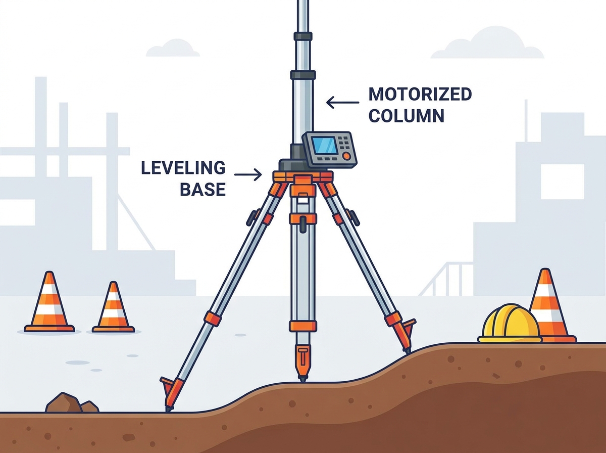
Maximize the footprint angle without exceeding the structural limits of the tripod legs to ensure a stable base. Set the legs into the ground using body-weight stepping on foot spurs to prevent settling or sinking during operation. We spread the legs to their maximum locked position for any deployment over 15 feet. You must drive the foot spikes deep into the soil. Stand on the foot spur of each leg and apply your full body weight until the spike is buried to the hilt. If you hit rock, shift the setup location slightly. We use heavy rubber foot pads when setting up on finished concrete to prevent slipping and protect the surface. Ensure the center column is roughly plumb by eye before moving to precision leveling.
Ground Surface Anchoring Protocols | ||
Surface Type | Anchoring Method | Spreader Plate Required? |
|---|---|---|
Concrete/Asphalt | Rubber pads, sandbag ballast (50 lbs per leg) | No |
Compacted Soil | Standard foot spikes driven to hilt | No |
Loose Sand/Gravel | Extended spikes, heavy sandbag ballast | Yes (12x12 inch minimum) |
Mud/Soft Clay | Engineered cribbing, deep earth anchors | Yes (24x24 inch minimum) |
Use manual tripod leg adjustments to achieve a rough level. Utilize tribrachs, built-in bubble levels, or integrated digital levels to ensure the mast is perfectly vertical before elevation. Elevating a mast that is off-axis introduces mechanical risks like asymmetric wear, binding, and a high risk of tipping. Allow the tripod and its precision payload to adapt to ambient outdoor temperatures to prevent material expansion or contraction from throwing off the initial level. We spend extra time on this step. You must adjust the leg lengths until the circular bubble is perfectly centered. Then, use the fine-adjustment screws on the tribrach for precision plumbing. We let the entire setup sit for 20 minutes in direct sunlight before doing a final level check. Aluminum legs expand as they heat up, which will pull the mast out of plumb if you don't allow for thermal acclimatization.
Securely thread or clamp the scanner, camera, or sensor onto the mounting plate. Emphasize the mandatory use of secondary safety retention cables or lanyards. Route power, communication, and control cables down the mast symmetrically. Ensure cables have adequate strain relief and slack, do not snag on telescoping collars, and are positioned to avoid pulling the mast off-center. We always use a steel safety lanyard rated for twice the weight of the payload. Clip it to a structural hard point on the mast head, not just a plastic handle. You must manage the cables carefully during extension. We use velcro straps to secure the cable bundle to the mast every three feet. Leave a service loop at the base to accommodate the full extension height without putting tension on the connectors.
Maintain line-of-sight with the mast and payload at all times during movement when using remote controllers. Slower, controlled elevation speeds are required for heavy payloads to minimize dynamic torque, sway, and mechanical binding. Monitor visual, auditory, and tactile cues like motor strain hum or minor mast deflection as the mast reaches its upper limits. We never use the fast-traverse setting when a heavy scanner is mounted. You must feather the controls on the hand pendant to initiate movement smoothly. Jerky starts and stops create a whip effect at the top of the mast. Listen to the motor. If the pitch drops significantly, the motor is struggling against mechanical binding or excessive weight. Stop the ascent immediately and investigate. We always keep one hand hovering over the emergency stop button during any mast movement.
Wind loads on high-surface-area payloads induce rotational forces on the mast, compromising data accuracy and structural integrity. Re-check levels periodically during long-duration scans to identify ground settlement or structural drift. We watch the payload closely through binoculars during the first few minutes of operation at height. You must look for any rhythmic swaying or twisting motion. If the scanner is rotating slightly back and forth, the wind load is overcoming the torsional rigidity of the mast sections. Lower the mast immediately. We place a digital inclinometer on the base casting and set it to alarm if the base shifts more than 0.1 degrees. Ground settlement happens slowly, often caused by the micro-vibrations of the motor running or nearby traffic.
Define the exact height limits and wind-speed thresholds that mandate the use of secondary guy-wire stabilization systems. Anchor and tension guy wires evenly using tension meters, preventing uneven pulling forces that could distort the mast structure. We deploy a three-point guy-wire system for any extension over 20 feet, regardless of wind conditions. You must anchor the wires at a 45-degree angle from the mast for optimal stability. We use heavy-duty earth anchors driven two feet into the ground. Attach inline tension meters to each wire. You must tension all three wires simultaneously and equally. Uneven tension will pull the mast out of plumb and cause severe binding when you try to retract it. We check the tension every hour, as ground anchors can creep and wires can stretch under sustained wind loads.
Attach the guy-wire collar to the designated hard point on the upper mast section.
Walk out the three guy wires at 120-degree intervals to a distance equal to the planned extension height.
Drive heavy-duty earth anchors into the ground at the three anchor points.
Connect the wires to the anchors using turnbuckles and inline tension meters.
Elevate the mast to the target height, then tighten the turnbuckles evenly until the tension meters read the manufacturer's specified load.
Safe deployment of a motorized elevation tripod system depends on controlling the entire setup environment before the mast is extended. Ground stability, slope, overhead hazards, wind conditions, nearby vibration sources, payload weight, and extension height must all be evaluated against the manufacturer’s operating limits.
The tripod base should be fully spread, securely anchored, and precisely leveled before the payload is installed. Cables, safety lanyards, locking mechanisms, electrical connections, and emergency controls must also be inspected and arranged to avoid off-center loading or snagging during movement.
During operation, the mast should be raised and lowered gradually while operators monitor motor strain, structural sway, ground settlement, and changing weather. Guy wires and exclusion zones provide additional protection for elevated or heavy payloads. Reliable performance begins with a stable foundation and disciplined operating procedures.
A: High wind speeds increase the risk of tipping and induce torsional twist on the mast. Always consult the manufacturer's wind-velocity charts and lower the mast if thresholds are exceeded. Wind creates a massive lever arm against the elevated payload.
A: Sequential leveling ensures the mast is perfectly plumb. Elevating an off-axis mast causes mechanical binding, uneven weight distribution, and potential motor burnout. A plumb mast ensures the center of gravity remains directly over the base footprint.
A: Guy wires must be deployed when extending the mast to high altitudes or operating near the maximum wind-speed thresholds specified by the manufacturer. We also mandate them when deploying heavy payloads that maximize the system's load capacity.
A: Ground vibration from heavy machinery or traffic can cause the tripod legs to settle, compromising the level and inducing data jitter in sensitive payloads. It can also loosen mechanical fasteners over time.
A: An exclusion zone prevents unauthorized personnel and light machinery from accidentally bumping the tripod, ensuring structural stability and site safety. It also keeps workers out of the fall radius if a catastrophic failure occurs.
A: You must use large engineered spreader plates or heavy timber cribbing under each tripod leg to distribute the point load. Standard foot spikes will sink into soft mud, causing the mast to drift out of plumb.